We’ve hosted a webinar aimed specifically at non-ferrous melt analysis and our OES expert Jochen Meurs covered 5 key areas of non-ferrous OES. If you missed it, you can watch the recording here.
We gave those attending the opportunity to submit questions and these were excellent and required in-depth answers. In this article we’ve collected all the questions that related to calibrating your OES instrument. These are the answers given by Jochen Meurs.
Question: How do you choose the best measuring line (wavelength) for a specific element when calibrating the instrument? The one that might look a good choice for the reference sample might overlap with lines from other elements in your actual sample.
You describe a real problem that is one of many that arises because the references samples are artificially produced and don’t always reflect ‘real alloys’ all that well. At Hitachi, we strive to choose the emission lines that show no obvious overlap with other elements that are common in a certain material.
There is a mathematical approach that corrects for inter-element effects, and this does give adequate results at high sample numbers. Another way to minimize overlapping from different elements is to increase the optical resolution of the instrument (this is what we did with the OE750). This ensures the line separation is sufficient to avoid overlapping peaks between the analytical element and the interfering element. (When compared to our smaller OES models, the OE750 shows far less interference due to line overlaps).
Another source of deviation in the results are effects resulting from differences in the matrix, usually because of a high amount of a certain element. The most well-known instance of this is Zn in a Cu-base, such as brass alloys. Zinc has a low melting point which means that as the concentration increases, it cools down the plasma. This effect shifts the overall intensities obtained for these samples. A simple correction is difficult and it’s more common to use a special sub-program for these types of alloys. If this isn’t used, you are very likely to get a significant deviation for samples containing high Zn concentration.
Another factor affecting results that mustn’t be overlooked is the quality of the reference material itself. Not every sample or supplier offers the same confidence level. The reference sample is the product of round-robin and other testing and the final composition depends on the quality and quantity of these. If you study the determined errors of your reference samples, you might see that often the precision of inter-laboratory results is lower than typical instrument precision. Therefore, the certified value is called the nominal or consensus value, but not the true value.
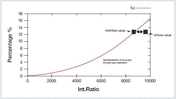
In the presentation, we discuss the how to use type-standardization and illustrate the effects with a graph.
Question: In type-standardization, you check a single point on the graph, but you move the whole curve (translation for additive). This is very dangerous as you do not know the impact at other concentration levels.
You are absolutely correct, and this is why I insist on two requirements:
Type recalibration (or standardization) is not for compensating for general errors in the calibration, or for measuring material that the instrument is not calibration for. Type calibration is for correcting minor deviations without touching the general calibration of the instrument. It is typically used when two parties (often the supplier and the user) agree on a certain sample for the reference and need to ensure comparable results from this sample on two different instruments. In this case, you can be more confident that the analysis of unknown samples similar to the reference chemistry are the same, despite possible systematic deviations in the calibrations of the two instruments.
Type recalibration is also a powerful tool when estimating error margins when using the error propagation according to ISO GUM (Guide to the expression of Uncertainty in Measurements).
Question: Please explain the difference between calibration, recalibration and drift correction.
Calibration: The measurement of certified standards and related specimens in order to calculate a regression as a mathematical function between measured light intensity and the corresponding concentration of a specific element in the sample. By knowing this function, the instrument can perform quantitative measurements on unknown material. This calibration is usually done by the OEM in the factory.
Recalibration: The measurement of ‘setting-up samples’ to compare the nominal values (obtained during the original calibration of the instrument) to the actual values obtained during the lifetime of the instrument. Differences between the values allows the user to correct for shifts in displacement and slope of the regression curve.
Drift correction: This can be another term for recalibration (used by other suppliers). Laboratories sometimes carry out a more advanced drift correction procedure. By measuring control (check) samples at regular intervals between analytical samples, you can monitor changes in the analytical results over time. Any changes detected can be applied to all measurements made between two control / check measurements. This eliminates long-term drift effects on the final analytical results and is usually a software exercise, using Excel or similar software.
If you’d like to see the recording of the live webinar Best 5 expert tips for optimal non-ferrous melt control with spark OES, you can watch it here.
In our new guide Optimal non-ferrous melt control with spark OES, we go into more detail on the optimum sample-taking process and preparation techniques to get reliable results first time when verifying non-ferrous melt chemistry. Download your copy by clicking on the link above or on the button below.
Get the guide Watch the webinar recording