Hydrogen fuel cells are experiencing significant growth, particularly in the commercial truck and bus sectors. Early indications suggest that fuel cells could become a viable and sustainable alternative to lithium-ion technology, playing a crucial role in our global transition away from fossil fuels.
Among the various types of hydrogen fuel cells, proton exchange membrane (PEM) fuel cells are particularly noteworthy. They are favored for their efficiency and versatility, making them suitable for a wide range of applications, from transportation to stationary power generation.
To ensure the long-term commercial viability of fuel cells, it is essential to maintain reliable performance by carefully controlling key parameters, especially temperature.
PEM fuel cells need to operate with a very specific temperature range – ideally within 60 to 80 ºC. If the temperature is too low, the cell won’t deliver enough electricity. If the temperature is too high, the cell can degrade quickly and performance will suffer.
Keeping the temperature within a fuel cell under control is no easy task. The process of turning hydrogen into electricity releases a lot of heat, and this heat needs to be managed carefully to keep the cell working properly. Because the fuel cell must operate within a narrow temperature window, it’s not enough simply to add a large heat sink. The temperature profile across all the elements of the fuel cell must be thermally modelled, including the active layers such as the ion exchange membrane, catalyst layers, the gas diffusion layers, and the electrode plates. The distribution of heat within the fuel cell depends on thermally conductive elements, making thermal mapping an essential part of the design process.
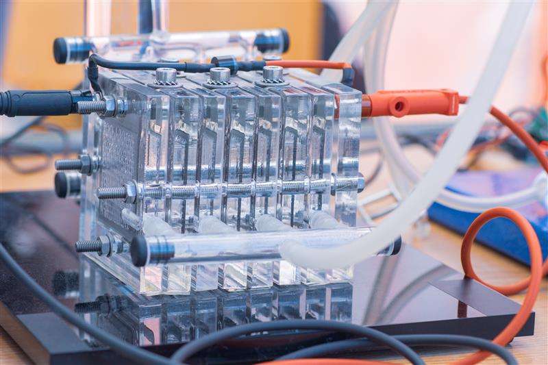
A PEM fuel cell generates electricity through a chemical reaction between hydrogen and oxygen. The core of the fuel cell is the proton exchange membrane, which is coated on both sides with catalyst layers – the anode and the cathode. These layers, along with other components, form the membrane electrode assembly (MEA).
Here's a step-by-step breakdown of the process:
The overall reaction produces water, electricity, and heat, making PEM fuel cells a clean and efficient energy source.
Once you have a thermally modeled fuel cell with optimally thick active layers for maximum efficiency and proper cooling, the next step is to manufacture them to precise specifications. Material analysis can help check that your production processes are meeting the design parameters. For example, X-ray analysis of the membrane electrode assembly (MEA) can identify contaminants or improper distribution of the catalyst (e.g. platinum) layer on the membrane. Such issues can negatively impact performance and lead to poor thermal management. In severe cases, you could get localized heating and thermal cracking, which could further negatively affect thermal transport across the cell. Material analysis can also help with failure mode analysis, checking for physical and chemical anomalies in cells that have failed or are performing poorly.
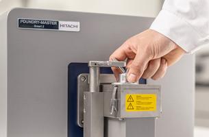
Hitachi’s EA8000 is a multi-analysis instrument designed specifically for the detection of metal contaminants and particle distribution deep within samples, such as membrane electrode assemblies. By combining X-ray transmission technology, optical microscopy, and energy dispersive X-ray fluorescence (EDXRF), the EA8000 quickly locates and characterizes particles over a large area.
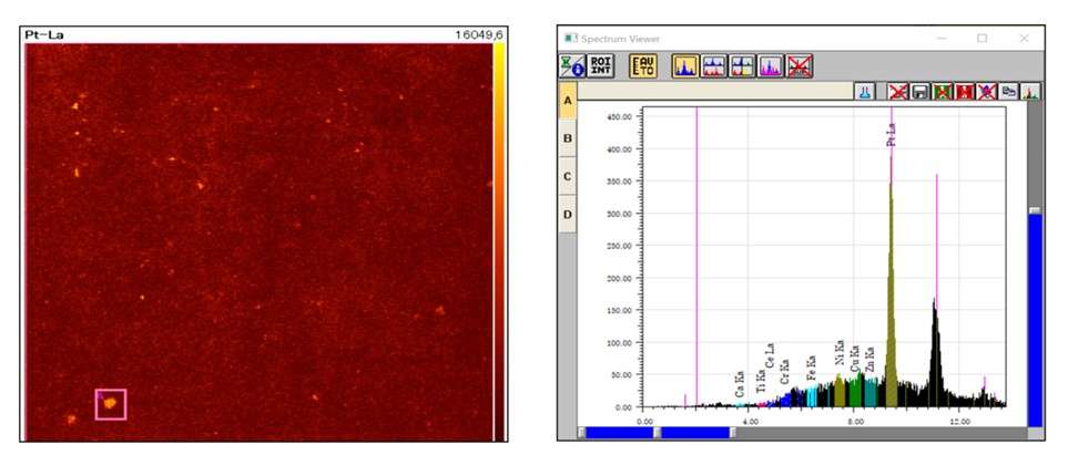
Example of results for platinum distribution analysis
To study the Pt coating distribution on the membrane, an EDXRF mapping of the entire sample (size: 35.9 mm x 35.9 mm) was carried out using a 5ms/pixel scanning speed, taking only 14 minutes to complete.
The EA8000 mapping results above show that Pt was not distributed homogeneously over the sample surface, and that it has formed clumps in some areas. This could potentially lead to poor fuel cell quality and premature failure.
Example of results for iron contamination analysis
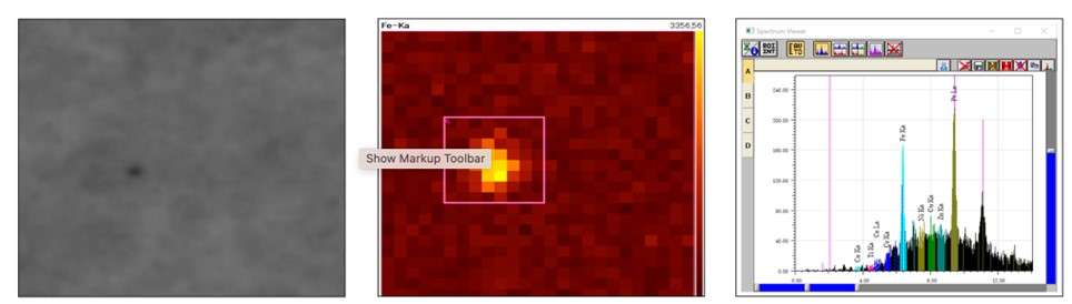
An iron particle of known size (diameter: 30 µm, thickness: 20µm) was deposited under the membrane and gas diffusion layer to establish if the EA8000 could detect and identify it.
Firstly, the analyzer detected the presence and the location of the particle under the material. It is clearly identified as a darker spot in the X-ray transmitted image to the far left above. The EA8000 then automatically performed an EDXRF mapping of the contaminated area, which confirmed the nature of the particle in less than 40 seconds.
The EA8000’s versatility enables operators to not only detect contaminants but also confirm the Pt (and other elements such as Ce) distribution on the membrane, to ensure fuel cell quality and durability while minimizing production costs and waste. A significant advantage of the EA8000 is that it can analyze contaminants beneath the surface, within the bulk of the membrane. This is an important feature to ensure that the MEAs are safe to release into production.
By leveraging the advanced capabilities of the EA8000, manufacturers can achieve optimal thermal management of hydrogen fuel cells, supporting their long-term commercial viability and contributing to the global transition away from fossil fuels.
Find out more about the EA8000 for fuel cell quality control.