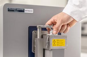
Getting accurate and reliable OES results for your non-ferrous melt verification process is not always straightforward. The presence of tricky to detect elements and the tendency for the alloy to segregate on cooling makes this task more arduous than for ferrous melts. This makes sample taking and verification a time-consuming process that must be repeated several times to control the melt to the level needed. However, it is possible to get reliable results in a single test, if you use the right techniques. In this post, we discuss the areas where you need to focus for good results.
It’s important to reduce the risk of segregation as much as possible when taking samples in aluminum and other non-ferrous alloys. For this reason, it’s essential to make sure that the liquid metal does not come into contact with any materials that may cause a chemical reaction and encourage segregation. This can happen if the melt comes into contact with any moisture, iron or dust. For this reason, the sample taking tools must be kept scrupulously clean. The same goes for the molds too, and keeping them free of crusts from previous samples will also help to speed up the cooling time – very slow cooling will make segregation more likely.
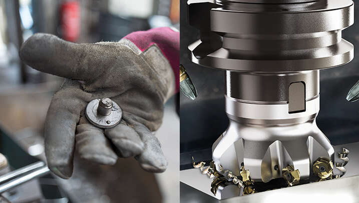
Any metal that sticks to the tools after solidification can indicate that an unwanted chemical reaction has taken place, so it’s always good practice to check tools after the sample taking process.
The optimal sample size and shape should allow for rapid solidification with no cracks, cold shuts, surface irregularities, inclusions or shrinkage holes. When taking the OES measurements, the distance from the analytical face to the edge of the sample must be right. And, the sample diameter and height must be kept to a minimum but be large enough to achieve reproducible results. These details should not be left to chance and the above parameters will need to be optimized for each alloy type before taking routine production measurements. Typical sample sizes (as given by EN 14726) are ∅ 40 mm × 30 mm (∅ 55 mm × 30 mm) for cylindrical samples and ∅ 50 mm × 10 mm or ∅ 55 mm × 4.5 mm for disc samples.
It’s also worth mentioning that the metallographic structure of the samples used to determine these parameters and as well the samples to check the accuracy of your spectrometer (control samples) must be similar to the production samples, as changes in these could cause systematic deviations in the results.
OES needs a plane, flat surface in the area where the sample is to be analyzed. This is preferably on the edge of the sample as segregation is more likely within the center. The best method of creating this flat surface for non-ferrous materials is by using a lathe or milling machine. However, once again, specific parameters must be determined to ensure the final surface is ideal for analysis. The surface roughness must not be too fine, and no sample material must stand proud of the machined surface. It’s also critical that no single hard grains are torn from the soft microstructure. This means that cutting speed, cutting angle and the cutting tool itself must all be tested on samples prior to routine production analysis to ensure the right parameters are found.
In our new guide Optimal non-ferrous melt control with spark OES, we go into more detail on the optimum sample-taking process and preparation techniques to get reliable results first time when verifying non-ferrous melt chemistry. Download your copy by clicking on the link above or on the button below.