Busy plating shops deal with components of many different shapes and sizes, and you’ll be aware that your XRF analyzer needs to be set up properly every time you make a measurement on a new type of component. However, out of all the parts that need analysis, irregularly shaped or curved samples can be the most challenging for getting reliable results with XRF. To explain why, let’s take a quick look at the internal components of your XRF instrument.
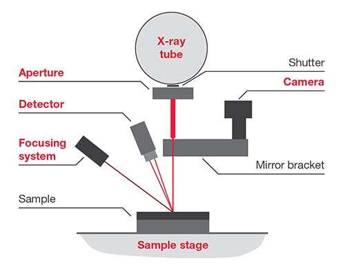
Without going into the details of how XRF works too much, with reference to the above diagram, the following is important:
Parts with irregular shapes, textured or curved surfaces pose more of a challenge because it’s much more difficult to ensure the two points above hold for every measurement. A curved surface means that the distance between the X-ray source, sample and detector will change every time you reposition your sample. The same issue goes for maintaining a 90-degree angle – clearly with a curved sample you must be very careful that the area being analyzed in in the same axis as the X-ray tube and detector. The X-ray beam must hit the top of an apex or base of a concave section, not the side walls.
Extra consideration must be made for the sample positioning and setup if you’re dealing with complex or irregular shaped parts.
Focusing your sample at the beginning of the measurement is a critical step. It aligns the X-ray tube, sample surface and detector to the right place, with the correct distance between the three elements. If this is not done properly, then your results will be off: if the sample is too near the instrument will measure too thick, too far and the results will be too thin.
Some instruments have automated sample focusing and with some it’s a manual step. Either way, it’s essential for all parts to be in focus, but with curved parts this will need rechecking every time the part is moved.
If your sample moves at all during the analysis, then it’s likely to be out of focus or the X-rays could hit a side wall – both result in misleading coating thickness results. Securing your part is clearly the way to go, but again, this poses a challenge for curved parts that tend to roll around just when you don’t want them too.
We recommend two main ways of securing irregular parts: ‘the ball of clay method’ and 3D printed part .
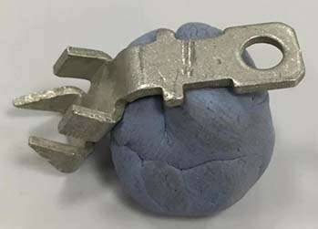
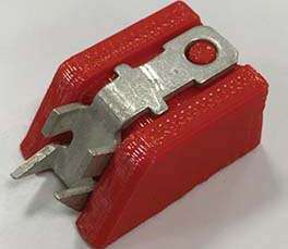
Ball of clay methodThis is not the best method, and probably only one you’d choose if you needed results fast or were measuring a one-off component. Basically, you press your part into a ball of clay and then do your best to get the measurement surface nice and level. It’s not perfect, but your part won’t move around while in the analyzer, which means you’ll be able to focus properly. | 3D printed part methodWith 3D printing, it’s relatively easy to make complex holders that present your awkwardly-shaped components flat to the XRF instrument. This is the method to choose if you have very tight error margins or have many irregularly shaped components of the same size and shape to measure. |
If you found this interesting and would like to learn more practical ways to ensure you get reliable results for plating thickness measurements with XRF, then you can download our free guide Understanding your XRF: A Guide for Plating Shops
In addition to analyzing samples of irregular shape, this comprehensive guide includes: