XRF analyzers come in many different types of configurations, giving you a huge range of options to choose from: detector type, optics type, automation and even between a benchtop or handheld instrument. In this post, we’re going to look at the challenges posed by measuring electronics coatings with XRF and discuss the best configuration for reliable and speedy measuring in a production environment.

Today, both handheld and benchtop instruments can measure metallic coatings thickness between 0.001 – 50 μm (0.05 – 2000 μin) on almost every type of substrate. The deciding factor between the two configurations is practicality rather than performance. If you are measuring very large components with relatively large areas of plating that can be seen easily by eye (and the instrument can be held in place easily by hand), then a handheld instrument is best for the job.
However, many electronics components are not like this at all. The features are extremely tiny and need to be located with a microscope and camera arrangement with the use of precision stage and specialized optics to ensure exactly the right feature is being analyzed. For electronics, benchtop is almost always the form factor to choose.
Deciding factor: The size of the part and the size of the feature being measured. Can you practically bring your part to the lab? If yes, you’ll need a handheld instrument. Do you need to measure areas smaller than 1 mm? If yes, you’ll need a benchtop instrument.
The aperture within your instrument directs and focuses the produced X-rays onto your sample surface. The resulting spot must be smaller than the features you need to measure and the optics you choose will be determined by your feature size.
XRF instruments typically come with one of two types of aperture: collimators or capillary optics. A collimator is a metal block with a hole and a portion of the X-ray signal passes through the hole to the sample. This is a good choice for measuring features 100 µm and larger. Capillary optics use specialized glass tubes that collect nearly all the X-ray signal and focuses it to a very small spot. This enables you to measure features less than 50 µm. This technology also gives better precision on thinner coatings as a higher proportion of X-rays is used when compared with the collimator configuration.
Deciding factor: Spot size. For features smaller than 50 µm, you’ll need capillary optics, larger than this, a collimator setup is probably fine.
There are two main types of detectors within XRF instruments, proportional counters and semiconductor-based detectors, and the silicon drift detector (SDD) is the most common semiconductor-based detector. Deciding which is best for your application can be tricky as both technologies have advantages in different situations.
Proportional counters are cylinders of inert gas that ionizes when bombarded with X-rays. They give excellent sensitivity for high energy elements like tin or silver and are very effective for simple analysis where you have few elements.
SDDs are semiconductor devices that create a specific amount of charge when bombarded with X-rays. They give better resolution when you are interested in several elements within a sample, or when detecting low-energy elements, like phosphorus.
The diagram below illustrates the difference in output from a proportional counter and SDD for the same sample. The red peaks show the SDD output, the grey spectrum is from the PC.
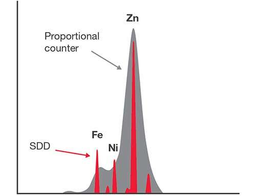
Deciding factor: It’s complicated, but if you need to measure several different elements or very thin or complex coatings, then an SDD is the best choice.
If you found this interesting and would like to learn more practical ways to increase the reliability and accuracy of your XRF analysis of minute electronics components, then you can download our free guide Understanding your XRF: A Guide for Electronics Plating
In addition to discussing the best XRF technology for your application, this comprehensive guide includes: